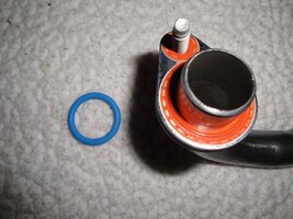
Oil Pump, new style versus old style,

JayArr

Member
Sep 24, 2018
544
Mission BC Canada
Hi All

I'm swapping in an engine I bought from the wrecker for an engine that blew the head gasket and warped the head.

The vehicle is a 2005 Envoy XL LL8 (inline 6) and the new engine is from a 2003 Trailblazer. The engines were identical until today.

I noticed on Rock Auto that the rebuild kits for oil pumps refered to a "second design"

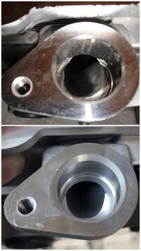
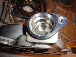
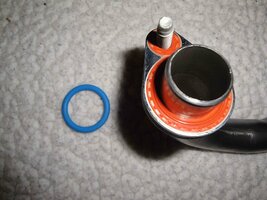
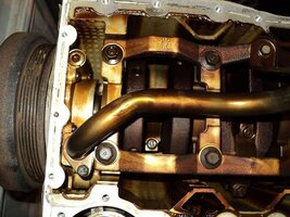
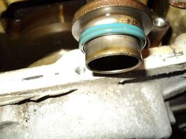
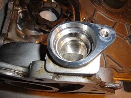
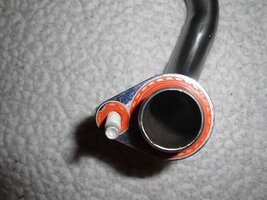
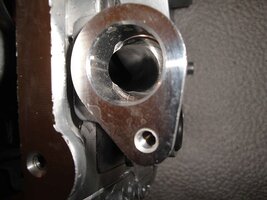
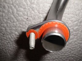
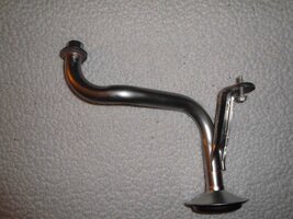
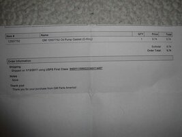
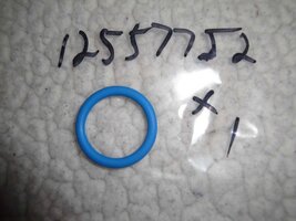
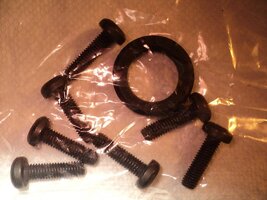
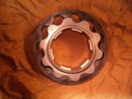
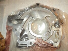
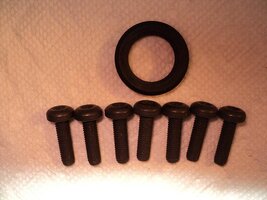
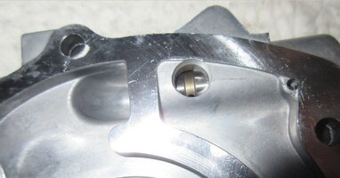
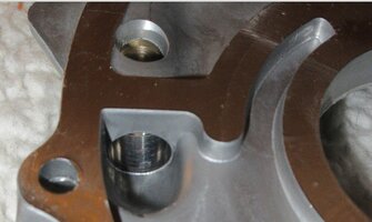
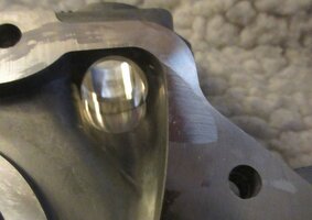
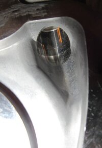
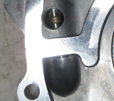
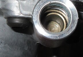
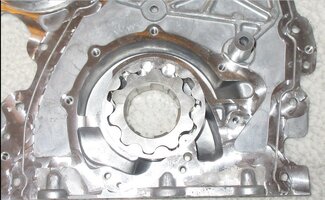
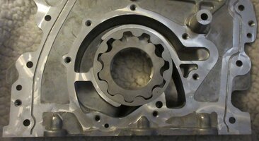
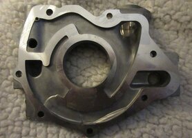
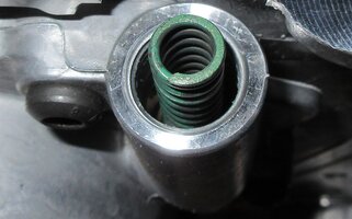
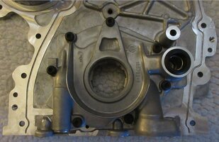
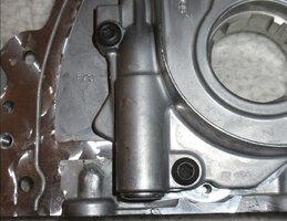
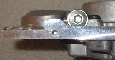
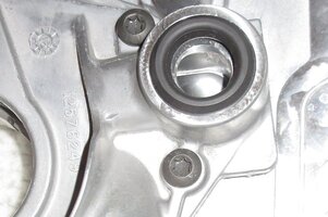
When I pulled both of my engines apart I see a difference and I'm inclined to assume that the picture with the blue O-ring is the second design while the picture with the orange washer was the original design.

Can someone confirm this to be true?

Next question... when did the second design come out? Is finding it in an 03 a sign that someone has worked on this engine before me?

JayArr
 

Attachments

  • PA070017.JPG
    PA070017.JPG
    418.7 KB · Views: 19
  • PA070018.JPG
    PA070018.JPG
    393.7 KB · Views: 18
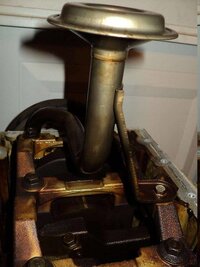
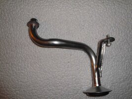
That is interesting....I wonder why the pick up tube (?) on the second one is shorter. Maybe @MRRSM can help shed some light?
 
  • Like
Reactions: mrrsm
AFAIK, The flat face design is the newest one. My 02 with the 03 engine had the old O-ring design. Why it was changed is unknown since the LS engines continued to use the O-ring. I think there were some reports of leakage on the early engines due to improper assembly and damaged O-rings.

Since you took it apart, you should put a new O-ring.
 
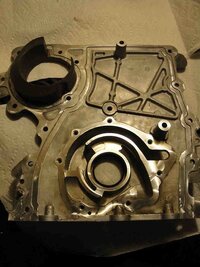
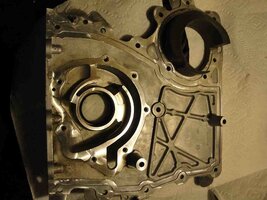
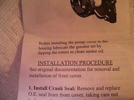
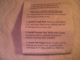
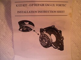
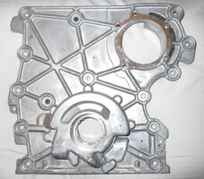
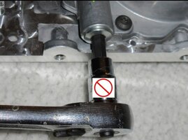
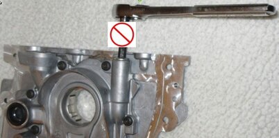
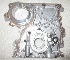
+1 ---^--- ...The distinctions between the Old Front Cover and New Front Cover (Both having the Gerotor Oil Pumps Screw-Head Bolted to the inside lower portions of the Covers) are significant. In this first series of images ...you can read the installation instructions that make the comparison of the two designs very well… and for good reasons:

(1) The Original (OLD) Style Gerotor Pump used a very shallow insert tube portion of the Oil Pickup Tube and also employed a Blue PTFE Sealing “O” Ring mating to the shallow, submerged “O” Ring Groove in the Base of the Gerotor Oil Pump to establish a vacuum seal.

(2) The problem however with the Early Model TBs and Envoy LL8s sporting the OLD Oil Pump/Oil Pick Up Tube Design of their mate ups areas was that in some cases… Air Cavitation occurred due to the Blue “O” Ring either getting nicked or cut during the factory OEM Assembly and later flattening out and allowing for a serious loss of suction leading to an inability of the Gerotor Oil Pump Gears to vacuum Crankcase Oil up inside of the Gerotor Gears and provide constant Oil Pressure.

(3) The solution GM worked out was to completely re-design the NEW Oil Pump Pick-Up Tube interface to include expanding the side of the mating flange surfaces meeting up at the bottom of the Gerotor Oil Pump Tube Manifold and eliminate the Submerged “O” Ring Groove and Blue “O”Ring entirely in favor of having a Longer Insert Extension Depth on the Tube penetrating much deeper inside of the GOP Manifold.

(4) And instead of using that Blue "O" Ring... GM opted to use a full-face Orange Teflon Coated Sealing Grommet Style Washer in the NEW Design ...behaving almost like a Ribbed, Water-Proof “Metri-pack” design to guarantee no loss of suction from around and in between the Deeper Set Oil Pick Up Tube and the inner workings of the Gerotor Oil Pump Gears. These Two Different Pumps and Pick-Up Tubes are NOT inter-changeable.

These are the Old to New Comparison Images and Install Instructions from my Photobucket:

http://s557.photobucket.com/user/60...AZERENGINEREPAIR/GEROTOROILPUMP?sort=3&page=1

...and the New Design as shown in my “Flickr” Bucket:

https://www.flickr.com/photos/12611.../126111508@N07/albums/72157671179967478/page2

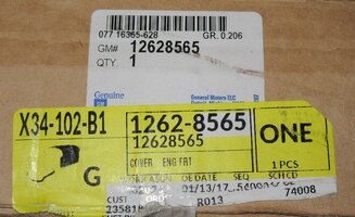
And if you need to research other New Parts and Pieces for your Re-Build… this link to my other images has a lot of data showing the parts I purchased along with their Make-Model-Part Numbers and Box Ends-Packaging Imagery for information on what to use during a Complete Engine Re-Build of the GM 4.2L LL8 Engine:

https://www.flickr.com/photos/126111508@N07/albums/72157671179967478/with/43350771592/

42494505745_234ac7eabe_z.jpg42494505965_d4f791ba11_z.jpg42681914194_3fd6b6dc60_z.jpg43350770822_f24af5ce29_z.jpg42494505865_f069e40fc8_z.jpg42681914204_08d9ca7d8e_z.jpg43350752342_de8cf5f26a_z.jpg43350770632_56bd86ecbc_z.jpg43350779592_1324cba187_z.jpg
 
Last edited:
It is funny because the LS engines continued using the O ring setup. My 07 Silverado has the O ring, and it did flatten and compress over time, starting to let it suck some air (particularly when the oil was cold), causing lower cold start oil pressure, some rather bad valvetrain noise, etc. I replaced that O ring this past spring and I almost never have cold start ticking anymore.
 
I would have never used a single bolt to secure the pickup tube. That's why I look at the second design as somewhat inferior. You'll never fully achieve full clamping pressure without two bolts opposite of center. Could have been a third design.
 
  • Like
Reactions: Redbeard
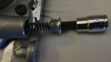
Both first and second design use a single bolt. On LS engines, the pump does have two bolt holes but only one is used, the one that's not accessible with the oil pan in place. This second hole is used as a hack to allow pickup tube re-installation without having to pull the oil pan. There is a kit available to add a second hold down on the LS.
 
Thanks for all the replies guys, if I had guessed I would have thought the blue O-ring model was the newer one, good thing I asked. I'll clean up the orange model pump and swap it into the 03 engine. Luckily I just got a case of Berkbile 2+2 Gum Cutter to get rid of all that varnish.
 
Guys, sorry to revive an old thread, but I had a quick question before I get too far into re-assembly. My replacement 2nd design timing cover has a huge chamfer compared with the images I see of the OEM. There is a chance that the inner tube diameter was just smaller, which exaggerates the chamfer... but I guess the important thing I'm trying to figure out is what is the diameter of the major diameter of the chamfer on the OEM pump inlet? The major diameter of the chamfer on my replacement cover is 1.000" exactly, and the teflon molded gasket on the 2nd design pickup tube is exactly 1.000". I thought that the gasket lip was designed to be flat on the face of the pump housing, but am I reading the above comment correctly, that it's more like a metr-pack interference where the Teflon kind of gets squished inside the chamfer? If so, that would explain why the diameter of the opening and of the teflon sealing lip are the same diameter. The Teflon ring on the gasket barely protrudes, I don't see how this is going to make a good seal at all. Does anyone have an OEM 2nd design timing cover handy and can see what the diameter of the opening is?
 

Attachments

  • Screenshot_23.png
    Screenshot_23.png
    573.2 KB · Views: 3
In the Second, Deeper, Smooth Bore Design, take note of the WIDER OUTER FLANGE SURFACE and invert your thinking about how this Orange Silicone Grommet actually functions: It is designed to resist PUMP SUCTION ... NOT ...OIL PRESSURE ...because the Pick-Up Tube must PULL FLUID from the lower Oil Pan nether-regions up and into the VACUUM Side of the Gerotor Oil Pump... so it is imperative that those Orange Silicone Seal *micro-lips* manage to get slightly pulled INWARDS around the Chamfer Perimeter as the Gerotor Pump functions... Like a School Kid pulling on a MacDonald's Soda Straw to draw in that last bit of Chocolate Milk-Shake from the bottom of the Cup!

If you were to make a -=small slit=- anywhere along the length of that Soda Straw from just above the level of the Milk-Shake Fluid... there would be an instantaneous Loss of Vacuum ...and NOT A DROP of the Shake would travel up and through that Straw.

Same Principle in This Case.

**** Capillary Action keeping the Molecules of Oil *Sticking* together --AND-- the necessary Vacuum created by the Crankshaft Driven Gear Lobes of the Gerotor Oil Pump ... Guarantees that whatever Motor Oil that is present in the Crank-Case-Oil-Pan... WILL circulate at 65 PSI around the Oil Galleries and Bearing Surfaces @ 11 Gallons Per Minute throughout the entire Oiling System with a nominal quantity of Motor Oil available being 7 Liters inside of the Pan and Oil Filter.

Everything works BACKWARDS on the DRAW SIDE of the Gerotor Oil Pump.

Hope This Helps...

**** Capillary Action WIKI

 
Last edited:
Do you have links to the exact parts you ordered? I assume this is for your 2002 'Voy? If you replaced the oil pump/timing cover with the second design for 2003+, you must also replace the pickup tube and screen to work with the flat gasket.
 
In the Second, Deeper, Smooth Bore Design, take note of the WIDER OUTER FLANGE SURFACE and invert your thinking about how this Orange Silicone Grommet actually functions: It is designed to resist PUMP SUCTION ... NOT ...OIL PRESSURE ...because the Pick-Up Tube must PULL FLUID from the lower Oil Pan nether-regions up and into the VACUUM Side of the Gerotor Oil Pump... so it is imperative that those Orange Silicone Seal *micro-lips* manage to get slightly pulled INWARDS around the Chamfer Perimeter as the Gerotor Pump functions... Like a School Kid pulling on a MacDonald's Soda Straw to draw in that last bit of Chocolate Milk-Shake from the bottom of the Cup!

If you were to make a -=small slit=- anywhere along the length of that Soda Straw from just above the level of the Milk-Shake Fluid... there would be an instantaneous Loss of Vacuum ...and NOT A DROP of the Shake would travel up and through that Straw.

Same Principle in This Case.

**** Capillary Action keeping the Molecules of Oil *Sticking* together --AND-- the necessary Vacuum created by the Crankshaft Driven Gear Lobes of the Gerotor Oil Pump ... Guarantees that whatever Motor Oil that is present in the Crank-Case-Oil-Pan... WILL circulate at 65 PSI around the Oil Galleries and Bearing Surfaces @ 11 Gallons Per Minute throughout the entire Oiling System with a nominal quantity of Motor Oil available being 7 Liters inside of the Pan and Oil Filter.

Everything works BACKWARDS on the DRAW SIDE of the Gerotor Oil Pump.

Hope This Helps...

**** Capillary Action WIKI

Thanks for the detailed explanation! Yes, the straw analogy, I know we're talking negative pressure before the pump gears, let me try to explain a little better. 1st, (I'll attach a side by side image of my replacement vs and OEM image when I get home), either the chamfer is larger on mine, or, the bore diameter is smaller than OEM, this is a fact. I'm just visually comparing but not having an OEM cover in hand, I can't compare with measurements, the chamfer appears huge comparatively.. that's what raised red flags initially. I think I dry fit the tube and it was fine inside the bore, can't remember though, I'll check again tonight and make sure it's a good fit, but we'll assume it's a good fit. I have the Melling 358s tube fwiw. Just my observation on the gasket and mating surface, at first glance, just looks very weak and prone to sucking air. Does this tiny 10mm bolt on only one side of the flange hold the flanges tight enough that the opposite side is not prone to leaving a tiny gap, allowing air intrusion, as you explained with the slit in the straw above the fluid analogy? I'm not torquing anything down until it's ready to be installed since it's a crush gasket, but just by eye, there is almost no substance to this gasket, the protruding ring is almost non-existent. Maybe I'm way over-thinking this, but I'm not pulling this oil pan again, I'd rather remove my fingernails with a hammer.🤣
 
Okay, looks like the bore is a little smaller than OEM as seen by the step/shoulder, that explains the larger chamfer. The tube isn't an extremely tight fit, but it's not loose either, there is enough play. If the design has the protruding, thin teflon ring sitting directly on the edge of the opening/chamfer, I guess I'm good to slap it back together, it just feel very.... unsubstantial. Here is the comparison....

1000038190.jpg
 
It is a rare moment when anyone has ever asked for "MORE INFORMATION" from any of my historical Threads and Posts... but it seems that in THIS case ... being "Visually Didactic" ...wont be seen as a Bad Thing:

What follows are -=ALL=- of my "Flickr-Bucket" images that demonstrate the profound differences evident below covering the 2002-2009 GM-GMC LL8 4.2L OEM Timing Cover & Gerotor Oil Pump-Pick-Up-Tube interfaces... Versus... The Later Model Updated Design Version.

Pay particular attention to the images showing the Two Covers standing side-by-side with their Pick Up Tube Interfaces close together so the differences can be easily compared.

And bear in mind that the Oil Pump Pick Up Tube is fitted with TWO Trapped Fasteners... NOT just the one adjacent the Insert Flange at the Gerotor Insert Point used to pinion that Tube solidly in place.

Sixty Images follow ...in batches of Twenty:

50109253108_898232f3c6_c.jpg50109823981_3f8445dcb5_c.jpg50109253133_c1269884db_c.jpg50109253168_20825e487c_c.jpg50109253138_56e5266194_c.jpg50110062267_aa7ce435e2_c.jpg50109253153_72b4020630_c.jpg49576291552_6023ea9bf7_c.jpg49576062871_d6eb44f377_c.jpg49576291607_9d850c51af_c.jpg49576063001_a9db397f35_c.jpg49576291647_d591778c33_c.jpg49575555913_e474ec601e_c.jpg49576291697_b5837ac7fb_c.jpg49576291702_6f539cfe43_c.jpg49575555988_4398ec2c8c_c.jpg49575555993_630d2b0ae3_c.jpg49576063156_dcc5eb0f0a_c.jpg
 

Attachments

  • 49576291827_0c3691c2f3_c.jpg
    49576291827_0c3691c2f3_c.jpg
    83.8 KB · Views: 0
  • 49576286922_f8199703df_c.jpg
    49576286922_f8199703df_c.jpg
    91 KB · Views: 0
Last edited:
Second Batch of Twenty Images...Continued:

49576058076_a537f60d70_c.jpg49576286977_b8614ccdab_c.jpg49576287002_21d17a86fe_c.jpg49576261842_b976d3651e_c.jpg49576033216_8af0f12bc6_c.jpg49576033246_836538d1e3_c.jpg49576033261_49388ceb6d_c.jpg49576261937_eb085e02b0_c.jpg49575526253_01c098d97b_c.jpg49576033331_b5941dab98_c.jpg49576033356_6240d6a61c_c.jpg49575526308_0b08c824a5_c.jpg49576033376_376f237fec_c.jpg49576262087_c470fde142_c.jpg49571670997_e257aaf471_z.jpg49571671107_f09eb7f8f5_c.jpg49571443541_ff81398319_c.jpg49571443616_30dab71f15_c.jpg49570937518_787173e8b7_c.jpg49571443736_2e402a3483_z.jpg
 
Third and Final Batch of Twenty Images:
 

Attachments

  • 49571443766_16683043e1_c.jpg
    49571443766_16683043e1_c.jpg
    57.8 KB · Views: 0
  • 49570937748_f074e19078_c.jpg
    49570937748_f074e19078_c.jpg
    71.6 KB · Views: 0
  • 49571443886_621344c4ed_c.jpg
    49571443886_621344c4ed_c.jpg
    62.3 KB · Views: 0
  • 49570937683_3ef5bdd6ab_z.jpg
    49570937683_3ef5bdd6ab_z.jpg
    35.5 KB · Views: 0
  • 49570937653_679b10b26d_z.jpg
    49570937653_679b10b26d_z.jpg
    85.1 KB · Views: 0
  • 49571671782_6c65790970_c.jpg
    49571671782_6c65790970_c.jpg
    100.5 KB · Views: 0
  • 49571671737_30d94a0b03_c.jpg
    49571671737_30d94a0b03_c.jpg
    98.6 KB · Views: 0
  • 49571444046_90b107f5a3_c.jpg
    49571444046_90b107f5a3_c.jpg
    69.9 KB · Views: 0
  • 49571671612_60039e875e_c.jpg
    49571671612_60039e875e_c.jpg
    75.8 KB · Views: 0
  • 49571444156_ec63122c13_c.jpg
    49571444156_ec63122c13_c.jpg
    72.7 KB · Views: 0
  • 49571444181_3124cceb92_c.jpg
    49571444181_3124cceb92_c.jpg
    69.9 KB · Views: 0
  • 49571671852_ae323e1f79_c.jpg
    49571671852_ae323e1f79_c.jpg
    55.7 KB · Views: 0
  • 49571671887_214cc94143_c.jpg
    49571671887_214cc94143_c.jpg
    104.8 KB · Views: 0
  • 49571444451_a47fee5bcc_c.jpg
    49571444451_a47fee5bcc_c.jpg
    83.1 KB · Views: 0
  • 49571444416_3dfaa58f17_c.jpg
    49571444416_3dfaa58f17_c.jpg
    97.4 KB · Views: 0
  • 49571444361_732893bbcf_c.jpg
    49571444361_732893bbcf_c.jpg
    105.9 KB · Views: 0
  • 49571671957_2a62a1016f_c.jpg
    49571671957_2a62a1016f_c.jpg
    68.2 KB · Views: 0
  • 49570938103_f7b14deaa6_c.jpg
    49570938103_f7b14deaa6_c.jpg
    76.6 KB · Views: 0
  • 49571672127_094c7fa751_c.jpg
    49571672127_094c7fa751_c.jpg
    115.5 KB · Views: 0
  • 142642-dcdb61595bfd12ed701d7c84eb635a30.jpg
    142642-dcdb61595bfd12ed701d7c84eb635a30.jpg
    13.7 KB · Views: 0

Forum Statistics

Threads
24,367
Posts
649,723
Members
20,950
Latest member
console

Members Online